
Programmable Logic Controllers (PLCs) have been the backbone of industrial automation, offering reliable control in challenging environments. While some experts suggest that PLCs are becoming less prevalent, they remain fundamental in many industries due to their dependability and real-time control capabilities. In this article, we’ll explore the essential components of PLC programming, focusing on the user program and operating system, to help you understand their roles in modern automation.
What are PLCs?
A Rugged Computer for Automation:
A Programmable Logic Controller (PLC) is an industrial computer built to withstand extreme conditions like heat, moisture, and dust. Unlike regular computers, PLCs are designed for reliability in manufacturing plants, power stations, and automated systems where downtime is not an option.
How PLCs Work:
A PLC monitors inputs, processes data, and controls outputs to automate machines and industrial processes. It replaces traditional relay-based control systems with a faster, more flexible, and programmable solution.
The Two Key Parts of PLC Programming:
Every PLC program is made up of two essential components:
-
The User Program – This is the set of instructions that tells the PLC exactly what to do. Think of it as a recipe that guides every action, from turning motors on and off to adjusting sensors.
-
The Operating System – This manages the PLC’s core functions, ensuring smooth execution of the user program. It organizes tasks, handles communication with other devices, and manages memory.
Even though PLCs aren’t as widely used as before, they remain critical in industries where precision, reliability, and real-time control are essential. Understanding PLC programming is key to optimizing automation and improving efficiency in industrial environments.
Operating System:
Think of the operating system as the boss of the PLC, in charge of arranging tasks and giving instructions to the PLC’s “brain,” called the CPU. However, it doesn’t directly supervise these tasks.
Here are a few things the operating system does:
1. It runs the user program, which is like the PLC’s to-do list.
2. It sets up a communication link for the PLC to talk to other devices.
3. It manages memory areas where important data is stored.
Why the User Program and Operating System Matter in PLCs:
Your PLC relies on two key parts to function properly: the user program and the operating system. These work together to process inputs, make decisions, and control machines. Understanding them is essential if you want to keep your automation system running smoothly.
1. The User Program – The PLC’s Instructions:
The user program is what tells your PLC exactly what to do. Think of it as a step-by-step guide that controls your machines. It handles:
- Reading inputs from sensors, switches, and buttons.
- Making decisions based on pre-set conditions.
- Sending commands to motors, lights, or alarms.
- Detecting and responding to errors or system changes.
You create this program, load it into the PLC, and it follows the instructions over and over without mistakes.
2. The Operating System – The PLC’s Manager:
The operating system runs in the background, keeping everything organized. It doesn’t control machines directly but helps by:
- Scheduling tasks so the PLC works efficiently.
- Managing communication with other devices.
- Handling memory to store and retrieve important data.
Without a well-structured user program and a stable operating system, your PLC won’t work reliably. Mastering both ensures your automation system runs smoothly and without errors.
Choosing the Right PLC Programming Method:
To make your PLC control machines and processes, you need to program it with clear instructions. Think of PLC programming as the language you use to tell machines what to do. The method you choose depends on your industry, application, and skill level.
PLC programming falls into two main types:
-
Text-Based Programming: This method uses written commands, like Instruction Lists (IL) and Structured Text (ST). It’s similar to coding and requires logical thinking and basic programming knowledge.
-
Graphical Programming: This method uses visual symbols and diagrams, such as Ladder Logic (LD), Function Block Diagram (FBD), and Sequential Function Charts (SFC). It’s easier to understand because it visually represents how the process works.
Which PLC Programming Method Should You Use?
Each method has its strengths, and the best one for you depends on your experience and what you need to automate:
- Ladder Logic (LD): Great for electricians and technicians because it looks like electrical circuits.
- Function Block Diagram (FBD): Uses blocks to connect logic, making it ideal for process automation.
- Structured Text (ST): Works like a programming language (similar to Python or C), perfect for complex logic.
By choosing the right method, you can program your PLC faster and make automation easier.
Understanding the 3 Main Types of PLC Programming:
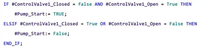
1. Structured Text (ST):
Structured Text (ST) is a text-based programming language used in PLCs, designed to be simple yet powerful. Unlike graphical programming methods, ST looks like traditional coding languages such as Python or C. It’s especially useful when working with complex logic, mathematical calculations, and repetitive tasks that would be difficult to represent visually.
How Structured Text Works:
Think of Structured Text as a way to “teach” your PLC using written instructions, just like coding for a robot. You can program it to:
- Perform calculations (e.g., multiplying sensor values to adjust machine speed).
- Make decisions (e.g., checking if a temperature is too high and triggering a cooling system).
- Repeat tasks automatically (e.g., looping through commands until a condition is met).
Since ST is purely text-based, it offers more flexibility and is ideal for handling complex automation logic efficiently.
Structured Text
Why Structured Text is Great for Beginners:
-
No PLC Programming Experience Needed
If you’re new to PLCs, ST is easy to pick up. It reads like a simple set of instructions, making it a beginner-friendly way to get started with automation. -
Simple, Text-Based Commands
You don’t need fancy software—just write your ST code in a plain text file and copy it into your PLC program. It’s as easy as writing a to-do list! -
Efficient & Lightweight
Because ST doesn’t use graphics, it runs smoothly on low-memory PLCs, making it a great choice for systems with limited processing power.
Final Thoughts:
Structured Text is ideal for logic-heavy automation where math and decision-making are key. If you prefer a coding-style approach over graphical programming, ST gives you the flexibility and precision needed for advanced PLC control.
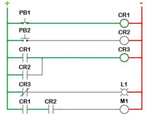
2. Ladder Logic (LD):
Ladder Logic (LD) is one of the most widely used PLC programming languages, especially in industrial automation. It is a graphical programming method that looks like electrical circuit diagrams, making it easy for electricians and engineers to understand. Instead of using lines of code, LD represents logic using symbols and connections, making automation more intuitive.
How Ladder Logic Works:
1. A Visual Programming Language:
Ladder Logic uses symbols and lines to create logical connections, just like an electrical schematic. Think of it as drawing a map that tells your PLC what actions to take. This makes it an easy-to-read programming method, even for those without a coding background.
2. Designed for Electrical Circuits:
LD is inspired by relay logic, which was used in traditional electrical control systems before PLCs. If you’re familiar with electrical wiring diagrams, Ladder Logic feels natural because it mimics the way relays, switches, and contacts work together.
3. Simple, Symbol-Based Logic:
Instead of writing complex code, you use symbols to define actions. These symbols represent different functions, like turning on motors, checking sensor inputs, or activating alarms. It’s like using building blocks to automate tasks.
Why Ladder Logic is Great for Beginners:
If you’re new to PLC programming, Ladder Logic is the best place to start. Here’s why:
- Visual Clarity – The graphical format makes it easy to follow and understand.
- Logical Flow – The program runs from left to right, like an electrical circuit, making it predictable.
- Real-World Use – LD is widely used in industries like manufacturing, power plants, and automation systems.
- Industry Standard – Many PLC manufacturers support Ladder Logic, making it a universal choice.
Advantages of Ladder Logic:
Self-Documenting & Easy to Read:
When you create a Ladder Logic program, you’re also creating its blueprint. The visual format makes it self-explanatory, reducing the need for extra documentation.
User-Friendly:
Since LD relies on pictures and symbols, you don’t need to be a coding expert. It’s like creating an automation story using visual elements instead of complex text-based code.
Faster Debugging:
Modern PLC software lets you see how power flows through your Ladder Logic program in real time. This makes troubleshooting easier, as you can visually track where an issue occurs instead of analyzing long lines of code.
Final Thoughts
Ladder Logic is the most beginner-friendly PLC programming language. If you’re looking for an intuitive, easy-to-learn method for automation, LD is a great starting point. It’s simple, widely used, and perfect for controlling electrical systems and industrial processes.
Function Block Diagram
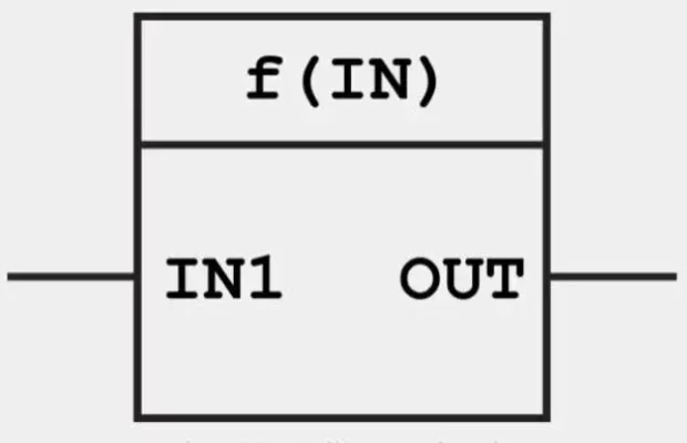
3. Function Block Diagram (FBD):
Function Block Diagram (FBD) is a graphical PLC programming language that represents logic using blocks instead of text or ladder diagrams. It is commonly used in process automation and industrial control systems because of its simple, modular, and reusable structure.
How Function Block Diagram Works:
1. Block-by-Block Logic:
Think of FBD as solving a puzzle. Each block represents a specific function, such as a timer, counter, or logic gate. The PLC processes these blocks in sequence, just like following step-by-step instructions in a visual format.
2. Connecting Functions Like a Flowchart:
FBD is built on connections. You take predefined function blocks and link them together to create automation logic. It’s like connecting puzzle pieces—each block does a specific task, and together they form a complete program.
3. A User-Friendly, Intuitive Approach:
Because FBD is graphical, it’s easier to read and understand, even for beginners. You don’t need advanced coding skills—instead, you drag, drop, and connect function blocks to program the PLC.
Why Function Block Diagram is Great for Beginners:
- Visual Programming – No need for coding, just connect function blocks like a flowchart.
- Easier to Debug – Since FBD is graphical, troubleshooting is faster than scanning through lines of code.
- Widely Used in Process Automation – FBD is common in industries like water treatment, HVAC, and chemical processing, where multiple control functions work together.
Advantages of Function Block Diagram:
Reusable Code for Faster Programming:
Function blocks can be reused in different programs without rewriting logic. Once you create a block, you can use it multiple times, just like a set of building blocks. This makes programming faster and reduces errors.
Standardized & Universal:
FBD is supported by many PLC brands, making it a reliable choice for industrial automation. If you switch between different PLC manufacturers, FBD remains consistent.
Perfect for Complex Systems:
Unlike Ladder Logic, which is ideal for discrete automation (on/off tasks), FBD excels at managing continuous processes like temperature control, pressure regulation, and motor speed adjustments.
Conclusion:
Programmable Logic Controllers (PLCs) are tough computers designed for challenging environments, working perfectly even when it’s really wet or hot. The success of a PLC hinges on two things: the user program and the operating system. Understanding how these components interact and function is crucial, whether you’re just starting with PLCs or aiming to sharpen your skills. This knowledge is your key to mastering automation in any industrial setup.

Digital Twins in Robotics: 5 Things to Know
Robot digital twins are transforming the way robots are built, programmed, and maintained, and they [...]
Jun

Top 6 CNC Machine Trade Shows 2026
We’re halfway through 2026, and the most important CNC machine trade shows are still ahead. [...]
Jun

What is Time Sensitive Networking?
In modern manufacturing, robots, sensors, and motion control devices must be in total harmony with [...]
1 Comments
May
Torque Ripple in Electric Motors
Electric motors are designed to deliver smooth and continuous rotational motion, but in practice, fluctuations [...]
May
Series Elastic Actuators Explained
If engineers are building or deploying robots that operate around people, actuator selection becomes a [...]
Apr
Mobile Robot Battery: Swappable vs. Fast-Charge
Every minute a mobile robot spends off the floor is a minute of lost productivity. [...]
Apr