Diving into industrial automation? You’ll want to get familiar with PLCs—Programmable Logic Controllers. These are the brains behind your manufacturing line, making machines run smoothly and efficiently. If you’re aiming to boost your line’s performance or keep up with automation trends, understanding PLCs is crucial. This guide simplifies everything about PLCs for you: their role, how they function, and choosing the right one for your needs.
Ready to make your manufacturing smarter? Let’s explore PLCs together.
What is a Programmable Logic Controller (PLC)?
A PLC, or Programmable Logic Controller, is like the smart brain behind your manufacturing line. Imagine it as a rugged computer that controls your machines and processes. It’s tough enough to handle dust, moisture, and knocks, making it perfect for any factory setting.
What does a PLC do for you?
It watches over your production line, taking signals from sensors and switches, then decides how to run your machines based on the rules you set. This automation means your line runs smoothly, with less waste and fewer errors.
Why should you care?
Because a PLC can make your life easier. It boosts efficiency and quality on your line. You can change how things work with just a few clicks, no need to mess with wires or manual controls.
PLCs come in all sizes. Some are small and simple for basic tasks. Others are big and can be customized for complex operations. No matter your project, there’s a PLC that fits.
Getting to know PLCs is your first step to a smarter, more efficient manufacturing process. With the right PLC, you’re not just keeping up; you’re improving your production and paving the way for future success.
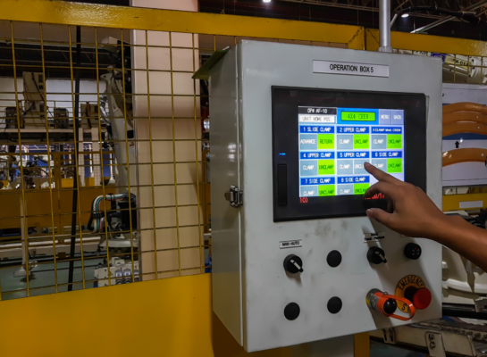
How does a PLC work?
Understanding how a PLC works is simpler than you might think. At its heart, a PLC follows a straightforward cycle that makes your manufacturing line smarter and more responsive to your needs.
1. Monitoring Inputs:
First, your PLC is always on alert, keeping an eye on your line. It checks every sensor and switch. This way, it knows exactly what’s happening, from the temperature of your products to when a machine starts.
2. Processing Logic:
After gathering input data, the PLC gets to work. It processes this information based on the logic you’ve programmed. This step is where the PLC makes smart decisions, like whether to cool a product based on its temperature. It’s the PLC’s brain, analyzing and deciding what action is needed next.
3. Acting on Outputs:
After deciding, your PLC gets things moving. It tells motors to run, valves to open, or belts to speed up or slow down. This is where your line adjusts to what’s needed, smoothly and without delay.
This cycle—watch, think, act—keeps going non-stop, making sure your line reacts right away. It’s quick, smart, and keeps everything running just how you want. Plus, changing things up is easy. Need to update your process? Just reprogram your PLC. This way, your factory stays up-to-date easily, without big changes or downtime.
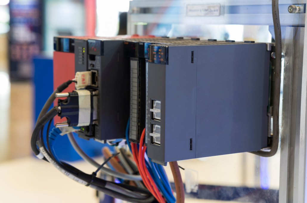
Key Components of a PLC:
The Brain: CPU
The CPU is the mastermind of your PLC. It processes your instructions, making quick decisions to keep operations smooth. It’s like the brain that oversees all actions on your manufacturing floor.
The Senses: Input/Output Modules
Inputs are your PLC’s eyes and ears, collecting data from around the factory. Outputs let your PLC act, driving gears and opening valves. Together, they’re the arms and legs of your system, turning decisions into actions.
The Fuel: Power Supply
Your PLC needs power, just like you need food. The power supply is its lifeline, ensuring it stays awake and active, ready to tackle any task.
The Messenger: Communication Interfaces
Communication interfaces are your PLC’s voice, allowing it to talk to other devices. It shares plans and coordinates with other machines, ensuring everyone’s on the same page.
With these components, your PLC becomes an essential tool for your production line. They work in harmony to adapt and respond to your needs, making your operations more efficient and responsive.
3 Main Types of PLCs:
Compact PLCs:
Think of Compact PLCs as the small yet powerful helpers for your line. They fit everything into one unit, perfect for when space is tight or your needs are simple. Imagine having a tool that manages a machine or a small process easily—that’s your Compact PLC. It’s great for small projects or if you’re just starting with automation.
Modular PLCs:
Modular PLCs are like customizable kits for your automation needs. You start with a basic unit and add what you need—extra inputs, outputs, or special features. They’re perfect for bigger, more complex tasks or when you think you’ll need to upgrade later. It’s like having a set of building blocks that you can rearrange or add to, matching your project’s growth step by step.
Safety PLCs:
Safety PLCs are the protectors. They come with safety features built in, keeping both people and machines safe. If your work involves heavy machinery, chemicals, or anything where accidents could be serious, you need a Safety PLC. They watch over safety sensors and stop everything safely if something goes wrong.
Each PLC type has its own role. Compact PLCs are for simple or small-scale tasks. Modular PLCs offer flexibility and growth for complex systems. Safety PLCs add an extra layer of protection for high-risk environments. Knowing what you need will help you pick the right PLC, ensuring your operations are not just efficient but also tailored to your specific requirements.
4 Types Programming Methods:
In industries, PLCs are used to automate tasks, and they need the right programming method. There are two main ways:
1. Graphical Form: This method uses diagrams, like electrical control drawings. It’s easy to understand.
2. Textual Language: This way uses words and sentences, like structured text or sequential function charts. It’s more flexible but needs more knowledge.
Understanding these methods helps you pick the best one for your job.
1. Ladder Logic:
Ladder Logic is like the starting point for PLC programming. Picture it as an easy-to-read electrical diagram, where symbols represent your commands. It’s straightforward: inputs lead to outputs, just like climbing a ladder. If you’re new here, Ladder Logic is your go-to. It’s ideal for making machines do what you want, in a way that’s simple to grasp.
2. Function Block Diagrams (FBD):
Think of Function Block Diagrams as playing with LEGO. Each block does something special—count time, add numbers, control a sequence. You link these blocks to shape your program. FBD is awesome for when things get tricky, helping you see the big picture of how your program flows. It’s your PLC’s flowchart, simplifying complex logic into manageable chunks.
3. Structured Text:
Structured Text is for the coders. It’s like typing instructions in a document, using lines of code to tell your PLC what to do. This method shines when you’re dealing with complicated calculations or need to juggle a lot of data. If coding feels like home, Structured Text will suit you fine, offering the precision for intricate tasks.
4. Instruction List:
Instruction List is the straightforward, list-making approach. You jot down commands, one after the other, guiding your PLC through each step. It’s the minimalist’s choice—no frills, just action. If you prefer a clear, linear path for programming, Instruction List keeps it simple and effective.
Every programming style has its place. Ladder Logic keeps it simple, FBD lets you visualize complexity, Structured Text caters to coders, and Instruction List strips it back to basics. Pick the one that fits your project and your comfort level the best, and you’ll find programming your PLC becomes a lot more intuitive.
Types of PLC Applications:
PLCs are your go-to for making industrial tasks simpler and smarter. No matter the size of your project, from a small shop floor to a sprawling factory, PLCs can make a big difference. Here’s how they fit into your work.
Machine Control:
PLCs are like the remote control for your machines. They start and stop conveyor belts, adjust motor speeds, and keep your production line moving just right. This means less waste and more perfect products for you.
Process Control:
When you’re mixing ingredients or keeping a close eye on temperatures, PLCs are crucial. They make sure everything happens at the right time, keeping your products top-notch and safe.
Automating of Assembly Lines:
PLCs can take over the repetitive tasks of putting products together. They ensure each piece is added at the right moment, speeding up the whole process. This cuts down mistakes and saves you money on labor.
Monitoring and Safety Systems:
Safety first, always. PLCs help here by watching for dangerous conditions, like too much pressure or heat. If things start to go wrong, they can sound alarms or even shut down equipment to keep everyone and everything safe.
PLCs are all about making your industrial operations smoother, safer, and more efficient.
Choosing the Right PLC for Your Needs:
Picking the right PLC (Programmable Logic Controller) for your project is crucial. It’s like choosing the right tool for a job—you need one that fits perfectly. Here’s how to make sure you get it right.
Understand Your Project:
First step: figure out what you’re automating. Simple task or big project? If it’s straightforward, a Compact PLC will do. But for bigger, complex jobs, you’ll want a Modular PLC. It’s all about matching the PLC to the job size.
Consider the Environment:
Where’s your PLC going to work? A dusty warehouse or a damp production area? Pick a PLC tough enough to handle your environment. Some are made to resist heat, cold, and even water.
Check Compatibility:
Your PLC needs to work well with your current machines and software. Make sure it can “talk” to your equipment. This saves you trouble and extra costs later on.
Plan for the Future:
Think about tomorrow. Will your needs grow? If so, go for a Modular PLC. You can add more features to it as your project expands, without starting from scratch.
Finding the right PLC means knowing your project, considering where it’ll work, making sure it fits with what you already have, and thinking about the future. Nail this, and you’ve got a winning component for your automation needs.
Conclusion:
Jumping into PLCs might seem big at first, but it’s a powerful step for improving your line. Knowing the basics, the different types, how to program them, where they’re used, and picking the right one is key. The perfect PLC does more than just make things run smoother—it grows with you. It’s about matching the right PLC to your needs. Use what you’ve learned to find yours and see how it transforms your operations.
Robot digital twins are transforming the way robots are built, programmed, and maintained, and they [...] We’re halfway through 2026, and the most important CNC machine trade shows are still ahead. [...] In modern manufacturing, robots, sensors, and motion control devices must be in total harmony with [...]
1 Comments Electric motors are designed to deliver smooth and continuous rotational motion, but in practice, fluctuations [...] If engineers are building or deploying robots that operate around people, actuator selection becomes a [...] Every minute a mobile robot spends off the floor is a minute of lost productivity. [...] 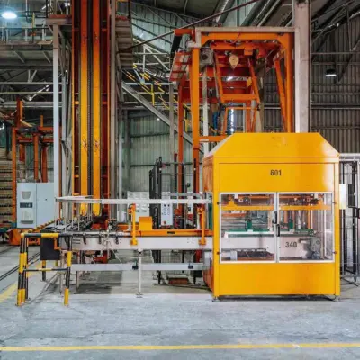
Digital Twins in Robotics: 5 Things to Know
Jun

Top 6 CNC Machine Trade Shows 2026
Jun

What is Time Sensitive Networking?
May
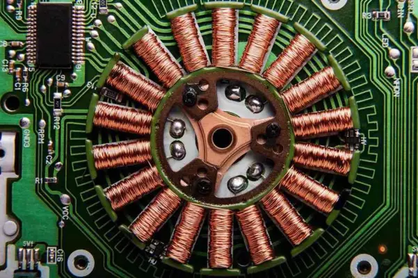
Torque Ripple in Electric Motors
May
Series Elastic Actuators Explained
Apr
Mobile Robot Battery: Swappable vs. Fast-Charge
Apr